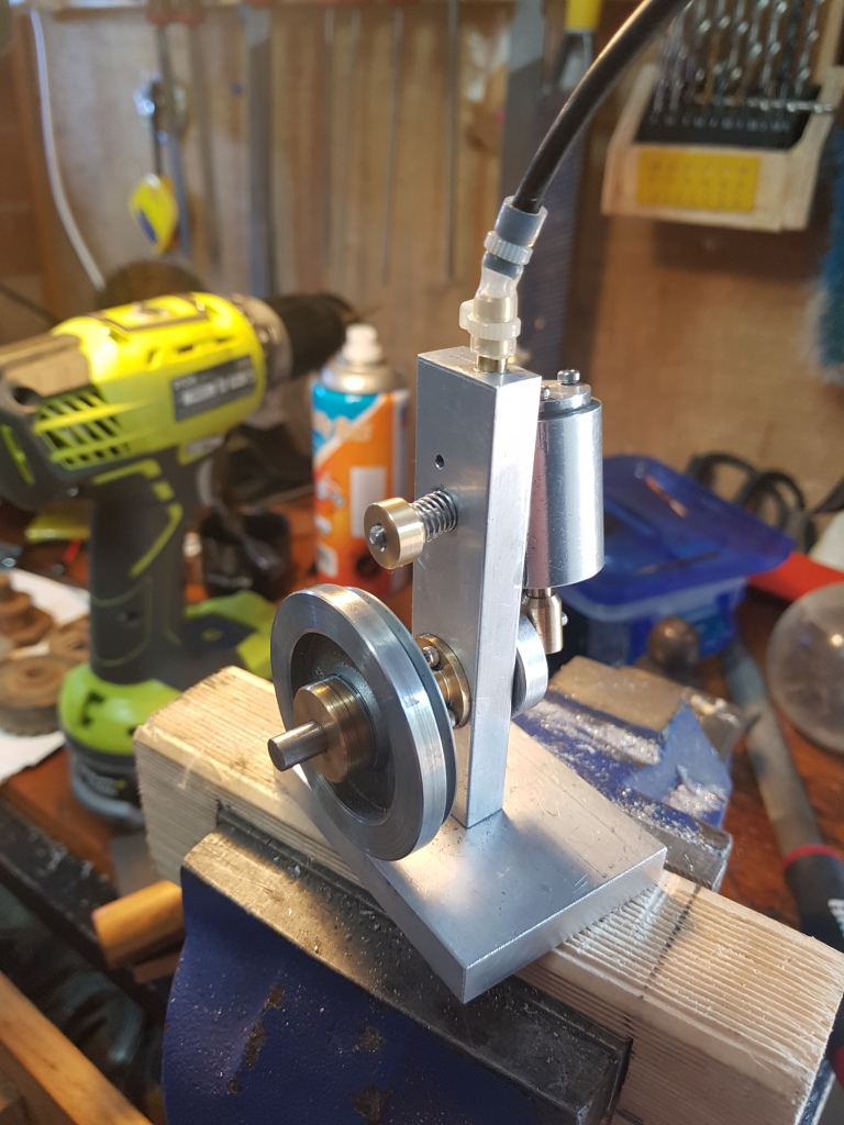
Victa lawn mower carburetor swap

This is going to be a short blog post, as the work I’ve done on this project was mostly in 2020. I found some video I filmed of me working on the mower, so thought I would throw it together and upload it.

I have an old Victa lawnmower, with a carburetor that was long past it’s used by date. I had replaced the mower with a new one at the time, and so figured I could mess around with the mower.

The carburetor is a Mikuni clone from ebay. They are generally found on motorbikes. I can’t remember the exact details, but I believe its for engines in the ballpark of the mower, which is about 160cc if I remember correctly.

I’m thinking of cleaning up the mower and maybe painting it, and making a bit of a project out of it. I’ll be sure to post details here.

Battery volt monitor for sound bag

It has been a long time since I’ve posted on the blog, but I thought I might try and post a couple of things. A lot has changed since last time I posted anything. We have had adorable twin boys, and we have moved house!

I’ve been working on a little project on and off for a while. I needed a way to power my Zoom F8n sound recorder from NP-F970 and similar batteries.

As I worked through the process, I’ve been through numerous iterations of the design, with different features and layouts, so I thought I’d share them for others, who might find them useful.

The basic design consists of a boost converter to take the 7.4v from an NP-F970 battery, and boost it up to 12v to power the recorder – a current sensor, OLED display and arduino to manage it all.

It started as a stripboard prototype holding an INA219 current sensor, and a boost converter, along with the connectors in and out of the unit. It was messy, but it worked.

After seeing it worked, I decided to try and make it a bit more professional, neater and more reliable.

This is where EasyEda circuit design software came into play. My first design was very much converting the stripboard design into the custom pcb. It’s fairly basic, but it allowed me to add a few extra things – Mainly Polyfuse protection, and I also replaced the 5v buck converter with an AMS1117-5 5V linear regulator to get 5v for the circuit.

This was literally my first attempt at making a PCB, so there was a few things done “wrong”, but it worked. Using EasyEDA and JLCPCB (not sponsored. lol), was so straight forward, and crazy affordable!

I’m linking to the OSHWLab of a slightly modified version of this board (ok,even after starting to write this post, I couldn’t help myself and made a few more tweaks). Things are laid out slightly different, and I’ve used a ground plane on the back instead of routing everything on on traces. This means I can make things a bit more direct, and clearer. There are some things that I would probably do differently in this version still, and maybe sometime when I have a chance, I’ll try and improve the layout – and maybe change up the labels to make things clearer

https://oshwlab.com/mruth/mixer-power-supply

The board is made to fit in one of these aluminium cases, and will be about 5mm short, but that gives a bit of room for the cables coming into the enclosure.

For this board to be of any use, you will need to connect an arduino microcontroller via I2C on the gnd/scl/sda/5v header area.

I didn’t have a PCB for the arduino (which is mounted with the screen in a 3d printed enclosure), everything was just wired point to point in the 3d printed case. I’ll link to the case below:

You can find the original case currently on Tinkercad Here if you want something you can easily modify or grab the STLs from Thingiverse HERE. it’s not perfect, but hotglue is your friend when it comes to holding in the screen

Arduino Code:

I’ve created a public Github repository, that can be found at the below URL. It is what should be the original version of my program. Having said that, I’m currently unable to test it as I’ve updated my test units to RP2040 Zeros. When I get a chance I’ll put together another arduino test unit to confirm that the code is working, and proceed from there.

https://github.com/RandoTheMagical/Soundbag-Powersupply-Original/

As I’ve mentioned earlier, I have several iterations of the design (mostly in drawings currently). I’ll probably upload those variations as a different post at a later date, and also probably another one for the current version I’m physically building. They are all basically the same architecture, but with varying configurations and additions. If this project is interesting to you, keep an eye out for my next versions.

Lathe Motor Upgrade

Amazing value motor for an amazing price.

The old Advance Lathe I have is awesome, but it’s a pain to adjust the speed of it, and you don’t get to much in the way of low speeds, you basically get fast, faster and really fast. Before I pulled the old motor off, I didn’t have a way of measuring the RPM of the spindle, but I’d hazard a guess that it spins at the top end of what it should spin at even on the lower pulleys.

The old motor looks a bit rough, but it seems in pretty good shape mechanically. I’ll be holding onto it until I find a more suitable project to put it it.

Wanting more options for speed adjustments, I decided to upgrade the motor.

There are several options for a new motor. The first being a 3 phase motor with a VFD. Even going with cheap motor and controller from ebay or similar, they get pricey quickly, and even on the bottom end of the motors, they output more power than is reasonable for this little lathe.

Another popular option is a motor from a discarded treadmill. It was a tempting option, as the price is usually virtually free, as a lot of them basically get given away. But then I’d have to mess around with mounting, controlling, finding a treadmill with a usable motor etc… it’s doable, but a fair bit of hastle.

I even looked at trying to run a high powered brushless motor made for radio controlled cars. you can get some pretty grunty ones these days and I found a hand full of people doing the swap online. Once again, it’s a hastle with mounting, controlling, reducing the speed etc…

The final option, which is the option I went with was a brushless motor configured for running industrial sewing machines. They are sold on Ebay and the usual places for Consew machines (and maybe a few others) The motors are 550 watts, or 3/4 horse power, which is a step up from the old 1/2 horsepower motor that was on it originally, but not so much more that I’m going to start breaking things elsewhere. More concern is the fact that the old motor is rated at 1440rpm, where the new one will do a maximum of 4500rpm, which is a lot higher.

For about $100 Aud, I got everything I needed to mount and control the motor.

The motor installation was pretty straight forward, thanks to the new motor coming with it’s own adjustable mounting bracket.

Mounting the motor was easy. The kit comes with a motor mount that pivots. Once I unbolted the old motor, I sat the motor in position, and got things lined up. You can move the motor in and out a little on the mount, which allows you to get the pulley aligned with the other one easily.

I had to drill an extra hole, and mount a bit of angle iron to get a bolt on the motor side of the mount, but it really didn’t take much effort or time at all.

The motor controller was mounted to a piece of wood, and then screwed to the lathe’s support with self tapping metal screws and an L bracket. The speed adjustment leaver simply screwed onto the left hand side of the lathe’s support, again with self tapping screws.

Here is a good shot of the motor controller and the speed adjustment leaver.

From new, the Advance lathes had a top speed of around 900rpm so my aim is to have it run at around that speed. It only has plain bearings, not roller bearings, so are a lot easier to damage.

The pulley on the new motor is a lot smaller than the one on the original motor. That is handy as it reduces the speed a little out of the gate.

Initially I didn’t have a way to check the spindle speed, so I was running the motor at around 2000rpm on the controller, and it was giving me a fast but not too crazy speed.

I borrowed a non contact tachometer from my work, which allows me to get an idea of the spindle speeds. Having a play around, on the lowest speed pulleys, I could get the motor to run between around 70 to 700rpm. This is awesome, as it allows me to use the full speed range of the motor, but sucks as it’s still running a bit slow.

By moving the belt up one pulley faster, the lathe’s spindle jumps up to around 1260rpm, which is a fair bit higher than ideal, but I can reduce the motor’s top speed on the controller, which hopefully should be sufficient.

Full speed on the second slowest is probably a bit fast, I’ll have to turn the speed limit on to prevent me from burning up the bearings in the lathe.

I’m going to have to use the lathe, and decide whether running the motor at full speed and associated torque is more beneficial than the higher spindle speed. Of course, I can swap between speeds if necessary. I’m hoping to be able to pick a setting to leave it at for most of the time though.

As far as operating everything goes, Basic operations are pretty straight forward. With everything turned on, moving the leaver to the left starts the lathe. Moving it all the way back to the right stops the lathe. I’ve read that some people who use these motors replace the hall effect sensor that controls the speed with a potentiometer, but I really like how this operates. Being able to start and stop with a quick movement feels great to me, so for the time being, I’m going to leave it the way it is.

You can adjust the upper limit of the speed by pressing the green up and down buttons on the motor controller (while the motor isn’t running). You need to delve into the menus further to do things like reversing the direction of rotation, or adjusting the lower limit.

The inability to reverse the motor easily is seen as s negative for some, but I couldn’t do that with the other motor, and as the chuck is just threaded on so I would likely spin the chuck right off if I tried to use it in reverse.

For those who are interested, I’m also attaching a scan of the instruction sheet that came with the motor:

That’s it from me for now. I hope this info is helpful to someone out there thinking of doing similar.

Cheers,
Matt.

Model Steam Engine

It’s taken almost 12 months to finish, but I’ve just completed my first somewhat complicated project on the lathe my dad gave me for christmas last year – A small wobbler style steam engine, based on the plans at http://www.steves-workshop.co.uk/steammodels/simpleoscil/simpleoscil.htm

The completed engine

The engine is built from aluminium for most part, with brass for some bits like the crank bearing, and the piston. This was mainly because aluminium is a lot cheaper than brass, and i figured I would make a few mistakes.

The flywheel was the only part I didn’t make completely from scratch. I believe it originated from a cassette deck I disassembled at some point in the past. It was the perfect size, so I decided to use that, instead of trying to find the materials to make one from scratch.

Firing it up for the first time was great. Seeing something that I made spin under its own power is a great feeling!

I haven’t extensively documented the creation of the engine, but I’ll show off some of the construction in the pictures below. I really need to get into the swing of documenting these things, so I can make more detailed construction blogs.

During the construction, I had a few issues, like breaking numerous drills and taps in the engine’s cylinder while fitting the cylinder head. I attribute these to poor experience on my behalf, and some of the drills I tried to use just happened to be super poor quality I’m afraid. That’s all OK though. This is a learning process!

In the end, while this engine isn’t the prettiest engine out there, it filled the goal I set out which was to build a functional working engine. I’m already working on my next engine, based on a modified version of the same plans. I do plan on spending a little effort on the next one finishing it a little more nicely, now I know I can pull off building a little steam engine from scratch.

Well, that’s it for now. I hope you enjoyed the blog.

Cheers.

Turned Aluminium Precision Screwdriver.

I have seen around some really neat precision screwdrivers, from brass and aluminium. They look great, but they are rather pricey so I wanted to have a go at creating my own version.

Ordinarily, I would have probably used a 1/4 inch hex bit, but the little 4mm hex holder / bits that I used for this project were lying around, So I decided to use that for my project.

This is my very rough measurements of the sizes of the hex bit driver. I explain things a bit in the video down below.

I have also made a video explaining some of the build process. It is a bit long, as I am also using it as a test of some live-stream capabilities, but I hope it provides enough info about how I’ve created it.

The driver has turned out really well. I’m going to trial it for a little while, and decide how I like it. If it works out OK, but needs some more tweaks, I’m tempted to attempt making another one. One thing I would probably change is the overall length. I would probably shorten it a little.

Thanks for tuning in, I’ll See you all next time.

Cheers.

Quick Leatherman bit adapter mod

This is only a quick mod, which I thought I would throw out there for those that are intersted.

The Leatherman bit extender / adapter is available to buy from Leatherman, but they are relatively pricey. Add to that the cost of the leatherman bits, and the price of things can get out of control fairly quickly.

I’m sure I’ve seen people do this on the internet previously, but it’s such a simple and great idea that I just had to give it a go.

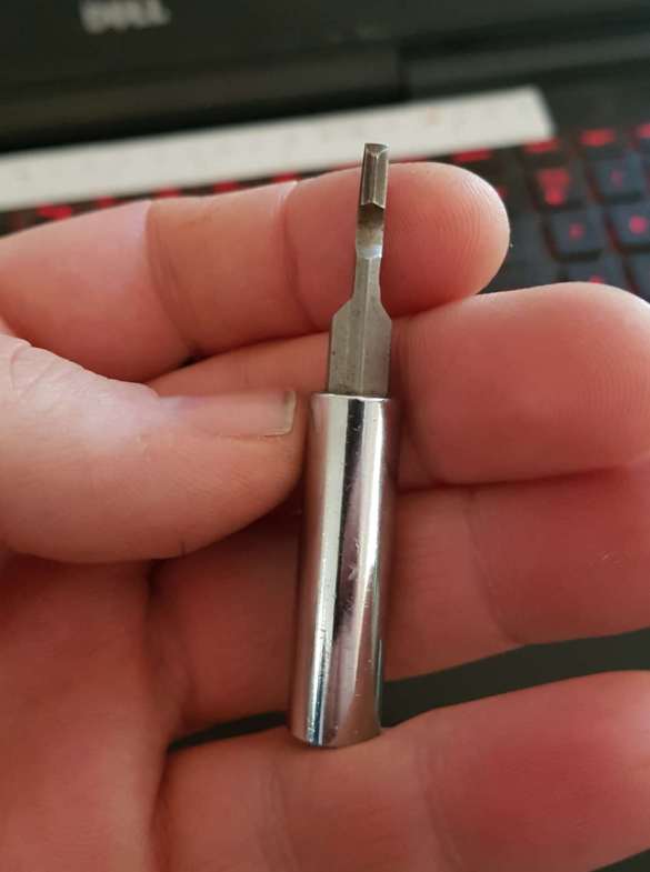
The Leatherman bits are simply modified 1/4 hex bits which are available virtually everywhere, so making an adapter simply involves grinding a flat on each side of a generic bit extender until it fits in the Leatherman’s screwdriver bit slot.

I used my belt grinder, but you could do the same with a bench grinder, an angle grinder, or if you are patient, probably even a dremel tool.


Hex Bit adapter


Hex Bit adapter

That is for this one. As I mentioned, this was just a quick post to show you one of the things I’ve been up to of late.

Now I have a Lathe

For Christmas, My Dad was nice enough to give me a metal cutting lathe. The Men’s shed he is a part of had it sitting around some time, and wanted to make some space.

This is the lathe in it’s entirety. As you can see in this photo, I’ve already added one of the Ebay quick change tool posts to it.

It is a Advance lathe – made in Melbourne Australia. They don’t seem to be too obscure, I’ve seen multiple references to them around the internet, which is handy, but they aren’t exactly as common as some of the other brands out there.

About the lathe

As I mentioned before, the Advance lathes were made here in Australia. They were manufactured in Melbourne from around the late 40’s, and were manufactured in one form or another into the 80’s. They are a clone of the popular Myford ML2 and ML4 lathes.

At some point, the lathe was given a fresh coat of paint, but you can still see the brass name plate showing through

Lathe.co.uk have a great write up on them, and many other vintage lathes which can be found here.

There is an archived version of another website with a wealth of info on them Titanium Studios Archived Page. It is always a shame when a good source of info regarding something like this disappears from the internet, but sometimes we are lucky enough for some of it to be archived elsewhere for prosperity.

Judging by the serial number stamped on the bed, This particular lathe was manufactured sometime before 1962, as it is stamped with the original manufacturer’s initials (AK – for Albert Kerby), and he sold the business and retired in 1962.

I’m guessing it was quite some time earlier than that, as from my reading, this lathe is a fairly early design. According to the lathes.co.uk site, features like the full nut on the leadscrew, and the dog clutch that are present on this machine were only features of the early models.

This lathe also has the split brass plain bearings in the headstock. I haven’t tried too hard to move them, but there doesn’t seem to be much play in them. I also left the headstock in place during my disassembly, as I was a little afraid of mis-aligning it when I put it back together.

I received the lathe with only only a 3 jaw self centering chuck, and a face plate, which is OK to get started, but I’m going to have to find a 4 jaw independent chuck at some point.

The headstock spindle is apparently threaded with a 1 inch bsf thread (10 tpi). I will note that while it is 10 threads per inch, aparently BSF uses a different angle thread, and chuck backing plates such as the one littlemachineshop sells (Part # 1791) is not suitable.

The bore on the headstock spindle is 17/32 inch.

The 3 jaw Chuck on my lathe is around 85mm. I’m  unsure if this is original or not. My reading suggests that there are a handful of older lathes around with 1 inch bsf thread, but it’s fairly rare. This makes it difficult to buy a backing plate for a new chuck that is ready to go. As such, when I get around to mounting a new chuck, i’m going to have to make a new one. This means I’m probably going to have to wait until I get a bit of experience before I attempt it. I’ll have to make do with the 3 jaw chuck for now.

If I understand correctly, the lathe has a Morse Taper MT1 in the tailstock, and a MT2 taper in the headstock.

My lathe is missing the change gears for thread cutting, everything to mound the gears, and the dog clutch to engage the gears. From my reading, the change gears for the Myford ML1- ML4 and ML7 lathes can be used with modification. I’m still trying to work that out. It would be awesome to be able to restore the power feed / thread cutting capabilities at some point.

Cleaning it up

The first thing I had to do before firing it up is to give it a good clean. It’s home for the last few years at least has been the welding area at the Men’s shed that me dad is part of. It hadn’t seen much use there because they have bigger and better lathes, but such an environment isn’t exactly the best place for any precision equipment.

When I started delving deep, there was years of crud built up underneath it, which all needed to be cleaned off. So, that’s what I did. I had the thing fairly well pulled apart, cleaned up, oiled and put back together in a couple of days.

years of gunk build up to clean out

As you can see, there was a lot of gunk to clean out

Pulling most of it apart allowed me to assess how worn things were, and from best as I can tell, this lathe has seen some use! there seems to be a reasonable level of wear on the lathe ways, and the leadscrew and it’s Full nut seem pretty well worn. Having said that, to me, a Lathe noob, I think it’s going to be serviceable to get me started in machining on a lathe, and is a wonderful little piece of Australian manufacturing history.

Hopefully I can learn a bit about restoring machinery like this along the way!

This process also allowed me to familiarize myself with the working parts of the lathe, and to understand what is missing. It is fairly complete, however, it is missing the gearing to drive the leadscrew for cutting threads. Actually, it appears to be missing more than that, the dog clutch mechanism that drives the leadscrew is completely missing. Actually, I suspect that the whole leadscrew at some point has been replaced. That’s OK. Having some level of power feed would be handy, as would thread cutting, but there are ways around the missing features, and some lathes, like the smaller taig and sherline lathes don’t actually have it.

In here there was originally a dog clutch that allowed for engagement of the leadscrew for gear cutting. It is missing, and I hope to attempt to make a new one

The missing gears do open the possibility for a future project in attempting to figure out the gears required, and scourcing (or making) a set of gears (and related clutch mechanism) to restore the function. The more I use the lathe, the more I realise having some kind of power feed would be very handy!

Time to turn some metal!

So, with everything cleaned up, oiled, and put back together, it was time to make some things. Delving into my odds and ends, I managed to find a bit of round rod, and what is closer to a really thick tube, to have a play with.

First cuts were a bit rough. My second attempts were better, but could be improved. I have a long way to go before I’m churning out high quality work I think.

Then, I figured I need to actually make something. I noticed the quill handles on my drill press were missing some of the little plastic knobs that went on the end. I figured I’d take a crack at making some replacements, using the one original as a guide.

I used some of the mild steel rod that I had to make the pieces. Aluminium might have been better, and wouldn’t rust, but we’ll see how a bit of oil on them keeps the rust at bay. The first one didn’t turn out so good. The second was better, the third about the same. I scrapped the first, and made a fourth to give a set of three acceptable ones. They were simply epoxied onto the chrome plated shafts. So far, so good.

My first project, you can see my first attempt on the left, and the right one is my second attempt.


All three new knobs glued on, and the handles fitted back to the drill

And with that, my first little project was completed. It was simple, and rough, but you have to start somewhere, right?

I look forward to the other little projects I can bring you in the future! I’m sure there will be many. Some of them might actually USE the lathe, instead of fixing or upgrading features on it!

I hope I can put together a bit of info on this lathe, for others who may encounter one. I doubt I can ever rival the linked posts, but the more info out there, the better. So, I’ll try and keep everyone updated on the blog.

Thanks Dad for the awesome Christmas present

Until next time, Adios!

Christmas Gifts – Hand made Knives

For a while now, I’ve been experimenting with making knives, having made a few knives for myself. There is a thriving online community in knife making, and it is gaining popularity as a hobby.

For Christmas this year, we decided to make some presents for people, and I decided to make some knives for different members of our family.

Today’s blog is more of a display of what  I have made. I do have quite a few process photos, so I hope to make a couple of individual process threads for some of these knives. This post is just a overall look at all of them.

Kiridashi

For my three sisters and my Mum, I made Kiridashi’s from 1075 high carbon steel. Two are straight steel, Two had a wood scale, held in with brass pins.


Fixed blade Knives

For my Dad, and one of my brother in law, I made fixed blade knives.

I made a sheepsfoot kitchen chopper style knife for my dad, with scales made of wood that he and mum found in their travels.

Again, they are made from 1075 high carbon steel.


My Brother in law got a sheepsfoot knife of a different design, with black G10 handle scales.


Slipjoint Folding knives

My Father in law, and other brother in law both got hand crafted slipjoint folding knives, They are linerless, with G10 scales, brass pins, and screw pivots. Again, the steel used is 1075 high carbon steel.


All the designs were new, and It took a lot of work, and I tried a lot of new things, and I think they came out great. I hope the recipients enjoy their new gifts, as while it was a lot of work to get them finished, I enjoyed making them!

Mic preamp for dslrs from old camera adapters


With the advancement of technology, It’s quite common for perfectly functional equipment to become obsolete, and essentially worthless. As is the case with Standard Definition miniDV cameras. They may work, and the professional ones like the Panasonic AG-DVC30 still look the part, but they have been left behind in history.

Attached to the top of most DVC30’s is a unit with the model number AG Mya30g. Just what is the AG Mya30g? Well it is an audio pre-amplifier, allowing the operator to connect professional XLR microphones to the camera, and to allow control over those Mics. It can supply phantom power to two XLR microphones, and provides you with a range of settings for the audio.

Here you can see all the controls over the audio you get with the preamp, and they are all useable with this easy mod.

These features include:

Mic / Line switching – Line level is useful if you wish to feed the camera with a line level output from a mixer. Mic level is obviously for microphones. The original article I’ve used for reference says that this is the input gain of the interface.

Attenuation switch – Useful for cutting the level from a microphone that is outputting a high audio signal that is clipping at the input. This can happen when recording loud noises, or using very sensitive microphones.

+48v – This switch activates the Phantom Power to the unit. Many microphones require phantom power, and this allows you to activate this power.

CH Select – This switch decides the routing of the microphones. It can be a little confusing, but CH1-2 patches the audio from XLR input 2 through to both output 1 and 2. This is usually used to send the onboard shotgun mic to both channels of the camera. The CH2 option patches XLR input 1 to one output, and Input 2 to the other output. This is the option to use when you want to use 2 different microphones, for example, the shotgun mic, and a lapel microphone.

Output volume knobs – Embedded in one end are two little dials, that allow you to adjust the output level of the module.

Now, you can see there are a lot of features here that are missing from modern stills first DSLRs and Mirrorless cameras.

I had a thought when I came across some of these cameras, what if someone was to figure out how to utilise this old but still valid technology, to allow it to be used with modern cameras?

Well, as it turns out, I wasn’t the first person to have this idea. I came across the blog at monterdiy.net

http://www.monterdiy.net/adapter-panasonic-ag-mya30g-jako-mobilny-przedwzmacniacz/

It’s written in Polish, but thanks to the magic of Google, you can translate it well enough to get the idea of what is going on.

And He’s done a whole lot of investigation, and got a lot of very useful info, like the fact that the preamp module has it’s own inbuilt power regulator that can accept a voltage from 3.6 – 36vdc.

He has even posted the pinout of the connector that is wired to the terminal block is also shown.

Which makes it really easy to wire things up.

Here is my interpretation of the pinout for the connector.


You could wire everything to the existing cable, and not even open the box (that’s what I did to test if it would work), but if you want a neater solution, you could do as I did, and slice open the insulation to extract the wires, and connect power and audio to the now much slimmer cables.

Before I got too far into this, I cut the multi pin connector from the cable, and wired iti up to power and half a 3.5mm audio cable.

Choosing how to power the unit was one of my first things to decide on.

Thankfully, with such a wide range of voltage input, things are fairly easy. Pick a battery in the voltage range provided, and see how it goes.

In my initial prototyping, I chose to go with 4x AA rechargable batteries.

They give a nominal voltage of 4.8v, providing a decent amount of room for voltage drop as the batteries depleat.

Once I had wired everything up though, I decided to move to a Sony NP-F550 style battery mount. That allows me to use the same batteries that I have for my LED lights. For a battery mounting plate, I used the top off a cheap battery charger. It holds the batteries firmly enough (but not as sturdy as a more expensive locking unit), and you can buy the entire charger for around $5, versus $20+ for a proper battery mount.

The NP-F550 battery fits really well on the unit. You could get away with the even smaller batteries with ease I imagine

For the connection to the camera, I simply cut a 3.5mm audio cable in half, and used one half, wiring it up to the appropriate wires from the unit.

The biggest issue I have with this unit, is that it’s difficult to adjust the gain on the unit on the fly. The gain controls are so small and hidden away. I guess it means that they won’t be bumped, but it’s still a pain.

Once I had everything wired up and working, I needed a way to mount everything to a camera. I came up with a pretty neat, and basic solution.

Here is a shot of the mounting plate with the 1/4 30 to hotshoe adapter attached.

I cut a square of aluminium I had kicking about, and taped a ¼ 20 hole in the middle of it. For long term use, I think the sheet is a little thin, and the thread might pull out, but for this initial testing, it works great. A small cheese plate from Ebay might work better, and allow more mounting options.

Into the aluminium base, I screwed a ¼ 20 to hotshoe adapter, allowing the whole unit to slot into the hot / cold shoe of you camera.

Everything is held together with hot glue for now. Hotglue sticks well enough for now, and allows me to change things if I desire later. Epoxy, or working out how to screw the components together would likely yield better, more permanent results, but I like to be able to tweak things in the future, so I’m a little hesitant to cover it in epoxy.

The preamp allows me to really turn down the internal preamps and avoid that Canon microphone hiss.

Testing with both my Canon EOS-M, and EOS-650d has yielded impressive results. I can turn the mic inputs in the cameras right down, and use the preamps in the Panasonic unit. This allows me to minimise the effect of the noisy preamps on the recordings.

So, now you can see, I have a great little microphone preamp that was destined for the scrap heap, but is now very useful again, with features often seen in products worth hundreds of dollars.

There are a few features that I may like to add to the unit in the future if I can figure out a way to do them without too much cost or effort.

A way to monitor the audio would be very helpful. As my cameras don’t have audio out, or permanent onscreen audio display, it can be hard to keep an eye on the audio levels you are recording. Splitting the mic output, and sending it to a headphone amp and/or VU meters would give some ability to monitor audio, even if it is only a rough idea.

Another thing that I may investigate is adding a port to the NPF battery sled, allowing me to run other items from the battery – specifically, my EOS-M, who’s batteries are small and run out quickly. This would be fairly easy to do.

Here we have the neat little unit, ready for use!

And that is about it as far as this build goes. I hope you have found this interesting, and if I have left out any details, let me know, or check out http://www.monterdiy.net/adapter-panasonic-ag-mya30g-jako-mobilny-przedwzmacniacz/ to get further details from the source.


How to use a Rode Videomic ME on your DSLR or mirrorless camera with a 3D printed microphone mount

I’ve been playing with the 3D printer again, and I’ve printed a shockmount for a Rode Videomic Me, with an integrated shockmount.

I’ve made a video of the device, which you can see here:

The original version of the clip can be found on Thingiverse HERE. Note that this isn’t my model, I was just fortunate enough to find a model that fits what I was trying to do perfectly.

The clip turned out really well, But I had to add a small square of double sided foam at the bottom of the spring part, I can dampen the vibrations that were present in the clip without it.

Once you have the microphone, and the shockmount, you’ll need a cable that adapts from the smartphone TRRS, to your camera’s input, which is generally a stereo TRS 3.5mm input. Thankfully, Rode make such a cable -The Rode SC3 – which for mycamera, is a perfect length.

If you want to save a few dollars, you can search on ebay or your favorite store for a similar cable. You’ll generally find ones with 2 male jacks, one for the microphone, and one for headphones. Just use the Microphone one, and tuck the other end out of the way

Here are a couple of ebay links to the two mentioned devices. They are Ebay Australia links, and I’ll stat that I have no affiliation with either sellers.

Rode SC3 adapter cable (an Australian store, selling for $15aud):
http://www.ebay.com.au/itm/RODE-SC3-3-5MM-TRRS-To-TRS-Adapter-for-Smartlav-/272084989754

Cheap ebay adapter (an Australian store, selling 2 for $5.95aud):
http://www.ebay.com.au/itm/2X-Female-to-2-Dual-Male-3-5mm-AUX-Audio-iPod-MP3-Headphone-Extension-Cable/122446560653

This setup works really well, and now I can use the microphone on my smartphone, and on my EOS-M, or other video cameras.

I hope you find this interesting, and will come back again soon.